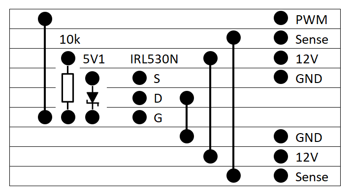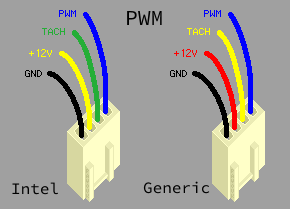

Although, adding a capacitor across the power lines with a PWM signal is cleaner, but that is another topic. This is exactly how 3d printers control their mainboard cooling fan (e.g. You can even pulse the power wires (it is still considered PWM) for low-power fans. Nitpickers will nitpick, but this has worked for ages for cooling fans in computers and 3d printers. This is how you find your power pins for the 3-pin and 4-pin PWM fans if you want to run them at 100% duty (no PWM signal at all - a floating pin). If you blow on a fan hard, it produces a voltage. Why does this work? If you power a typical (single-phase) DC cooling fan, it spins. You should only need to try this at most twice.

Next, with a can of compressed air (not by touching or blowing), get the fan spinning and see if you can observe something close to the 5V, 12V, or 24V (what your fan is rated for). So, to answer the OP's question and help Googlers years in the future, try this:Īttach a voltmeter to any two adjacent pins/wires (power pins are usually adjacent). I have four black wires on my 4-pin PWM Arctic and Noctura fans because I use my own PWM cables. Is it possible to disconnect this connector piece and connect the individual wires directly? (red and black?)ĭo you have red and black wires? I don't. If you interpret this differently, ask the OP to clarify. I interpret this as "I want to power my fan and have it running at 100% speed". Is it possible to disconnect this connector piece and connect the individual wires directly? (red and black?) I currently have a fan with a 4-pin connector that I want to power, but I do not have a power supply with a 4 or 8-pin connection. How to connect a 4-pin (3-pin) connector to a power supply? Even when following the diagram mistakes can happen so it is always good to test the cables prior to powering on your system.If you came here from Google with the question: We are not responsible for any damage that occurred because of the misuse or misinterpretation of our pin out diagrams. You’ll receive the file to download after the order is complete.Īs always, we recommend using a power supply tester to test your cables once you have made them.

View the example diagram to get an exact (without the correct pinout of course) view of what the diagram looks like. Save hours of work with our highly detailed and easy to follow pinout diagram! These diagrams are the same that we use when making our own custom cables for our clients so they are tested and accurate! Everything from which connectors to use and what pins require double wires is just some of the details we included for you making it easy to know which products you’ll need to make your own cables.


 0 kommentar(er)
